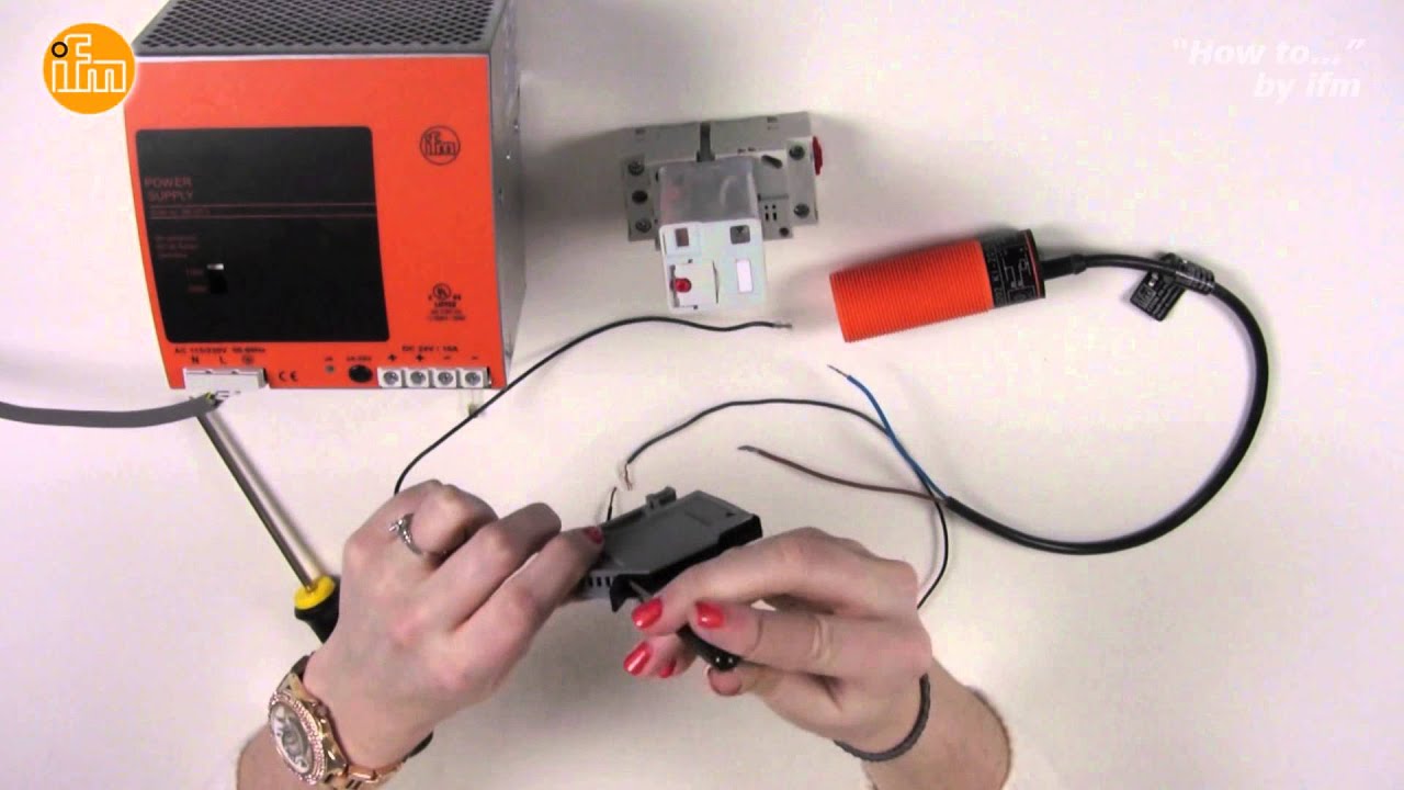
When it detects that target it operates an internal electronic switch. The wiring for the sensor goes like this.
Inductive Sensor Operating Principles
It is the same voltage that is sent to the axis encoder.

How to test a 2-wire proximity switch. Up to 9 cash back 10R5549. PNP Connect one lead of your meter to 0vdc and connect the other lead to the output wire of the prox input to the machine. Inductive Proximity Sensor Lj18a3 8 z axlj18a3 5 z ax Metal Sensor.
Click on the image to enlarge and then save it to your computer by right clicking on the image. If the negative terminal is. Because the sensor is an electronic device it requires a DC power source.
Wiring A Fan 4. On the inside NAMUR sensors have different circuitry than standard 2-wire DC sensors and need special treatment. The date lot code information will be displayed on your packaging label as provided by the manufacturer.
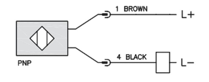
A SIGNAL wire usually a brown wire and a -SIGNAL wire usually blue. Two 2 prox switches option Figure 2. Hello I was reading about a 2 wire inductive proximity switch and i am little bit confused about how the switch generates the magnetic field.
Input cards do not know the difference between 2- 3- or 4-wire sensors but input cards for 2-wire sensors must be rated to accept the sensors voltage drop and off-state current level noted on datasheets Sensors with 3 and 4 wires have dedicated output wires. Due to approvals required for hazardous environments intrinsically safe sensor configurations require a. A power wire a ground wire and a switch wire.
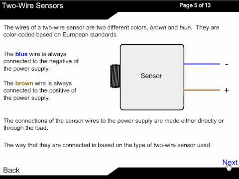
Sensors can also be broken down by their wiring configurations. I show you how to test and interface the sensor. Connecting the 2-wire sensor can be done by merely connecting the blue wire to the input and the brown wire to the 24V source.
In a 3-wire configuration two of the three leads supply power while the third switches the load. A 2-wire sensor of course only has 2 wires including a power wire and ground wire with connection options of Polarized. A 3-wire inductive proximity sensor is an electronic device that can detect ferrous Fe targets without any physical contact.
Essentially all inductive sensors need to have a magnetic field to sense some metallic object but how. When you see the cable coming out of the sensor turn red it means that metal was detected and the sensor has been switched on. The 3-wire 5 VDC sensor receives voltage from the processor PCB.
A 2 wire prox is designed to switch something otherwise it will not be useable so to bench test put a relay in series with the wiring which is the same concept for its normal use. Typically in factory automation applications 2 or 3 wire sensors are implemented within the process and as you know from my prior post a 3 wire sensor has the following 3 wires. In this case you would just connect the brown wire to the input and the blue wire to the ground of your power supply.
The most common are 2-wire and 3-wire. This circuit is for an unusually sensitive and stable proximity alarm which may be built at very low cost. Collection of 2 wire dc proximity sensor wiring diagram.
If the axis encoder works correctly and there are no encoder alarms the sensor. Troubleshooting a Proximity Switch with a Multimeter and an Oscilloscope The digital multimeter is the mainstay of electrical troubleshooting and the tool that most of us reach for first. For 12 VDC proximity sensors test the voltage at the proximity sensor.
Find More Posts by Gil47. To connect two sensors in series the SIGNAL wire of sensor 1 is connected to 24. In some cases the prox may drop the voltage by a couple volts.
Apr 03 A short tutorial on a 3-terminal PNP capacitive proximity sensor. In Beyond the Multimeter we look at five examples of how reaching for an oscilloscope next can make troubleshooting faster easier and more effective. Four 4 electromechanical switches option.
Calculate the bleeder resistance and allowable power using the following equation. Inductive Proximity Sensor 3 mm 2 Wire NAMUR 82 Vdc M12 Connector. When using an AC 2-Wire Sensor connect a bleeder resistor so that the Proximity Sensor current is at least 10 mA and the residual load voltage when the Proximity Sensor is OFF is less than the load reset voltage.
The diagram below shows the wiring connections for two 2-wire DC proximity sensors wired in series to various types of DSI 2 inputs. Make sure you check that the off state is 0vdc on your meter proxies usually fail on. As the name implies this type of sensor has two wires.
These output wires are run straight to a modules input. Upon detection of the target by the Schmitt Trigger the sensors output is switched on. Two-wire devices are designed to wire in series with the load.
The short animation to the right shows the effect of a metal target on the sensors oscillating magnetic field. Beyond the Multimeter Part 4. The process is the same for replacing a NPN 3-wire sensor.
On quick visual inspection a 2-wire NAMUR sensor looks the same as a standard 2-wire DC sensorBut do not confuse the wiring connections between these two types of sensors. For example 24vdc in and 22vdc coming out.
2 Wire Dc Sensor Working Principle Youtube
Wiring An Inductive Npn Pnp Sensor Click Plc Acc Automation
Two Wire Sensor Working Principle And Animation

3 Wire Inductive Proximity Sensor How To Read The Datasheet Realpars
Two Wire Inductive Proximity Sensors The Universal Donor

How To Wire A 2 Wire Ac Sensor Youtube

Sensor Basics Archives Automation Insights
Connecting A Two Wire Inductive Proximity Sensor To Arduino Uno General Electronics Arduino Forum
Two Wire Inductive Proximity Sensors The Universal Donor


Post a Comment
Post a Comment